In building the Upstairs Train, I ran into a number of problems and challenges due to its size and complexity. I pass on to you the lessons I learned in the hope that they will save you some time, frustration, and possible damage to your trains. These lessons fall into the following categories:
1. Preventing derailment when a switch is flipped the wrong way.
2. Independently running more than one train at a time in different "zones" when their tracks are interconnected.
3. Running a train in "mainline" mode through two or more zones.
4. Running more than one train around a single loop controlled by semaphores.
5. Preventing an engine from reversing directions after it has been stopped.
6. Designing a control panel that helps the operator keep it all straight.
After you read all that, read through the Summary, which ties it all together.
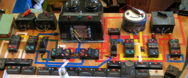
The blue to the left of center is the Lower Loop. The little bit of red and green mixed in with it are the red and green lines. The white lines, and the yellow lines on the left, are the rail yard and other sidings. That area is powered by the right side control of the large #18B transformer in the middle On the blue tape just to the left of the transformer is the black rocker switch that takes the lower loop into or out of mainline mode.
The yellow is the yellow downslope and the yellow line from the Northeast Corner to the Central Exchange. It is powered by the second transformer from the right (#8B). On the yellow tape between the switch controls, below the transformer, is the red rocker switch that takes the yellow line into or out of mainline mode.
The little blue loop at the right is the Upper Loop. It is powered by the transformer on the right (Gilbert #2). The red rocker switch at the lower left corner of that transformer takes the upper loop into or out of mainline mode.
The red is the red upslope and downslope between the Upper Loop and the Central Exchange.
The Central Exchange is powered by the left side control of the large #18B transformer in the middle. It is also that left side that controls trains in mainline mode.
The transformer at the left (#1-1/2) powers most of the lighting on the layout. I have connected the lights to the variable post so I can control the brightness of the lights.
The second transformer from the left (#22004) powers the aircraft beacons, oil derrick, and water tower that do not want to be on variable power like the other lighting. It also powers the #771 Operating Stockyard and #766 Guilford Station. My friend Eric Bense suggested putting them on variable power because the full power of 15 volts overdrives their vibrating bases. He was certainly right!
The string of control buttons at the bottom of the picture control the various Operating Accessories and the uncoupler on each siding.
It takes time and money to maintain a website like this. If you would like to contribute financially to its ongoing success, you may send a contribution via PayPal using theupstairstrain@yahoo.com as the payee. Both credit card and direct transfers would be gratefully appreciated.
Trains Engines Operating Accessories Bridges Towers Buildings
Crossings Construction Landscaping Lighting Semaphores Control Panel
Wish List History Useful Links

